
Map Stratigraphic Sections
To access this screen:
-
The Stratigraphic Sections screen is part of the Mapping task bar.
Note: The Stratigraphic Sections option will only appear on your system if your
system configuration
file contains a correctly defined <StratSections>...</StratSections>
area.
Typically, ground data is captured at the face in the form of vertical distance values (either upwards or downwards) from a known reference line. Typically, narrow reef operations that employ a conventional breast mining method follow a specific mapping workflow due to the nature of the mapping dimensions. A series of vertical “sections” are taken at defined intervals across the panel face in stopes, or along sidewalls in development ends.
Note: The Stratigraphic Sections panel is only available if creating a face map.
This map data type is typically created during face mapping.
The Stratigraphic Sections panel is used to log field data representing structural information about a face or wall. This data is logged as sample intervals of a drillholes data object, attributed to indicate a particular rock structure, for example.
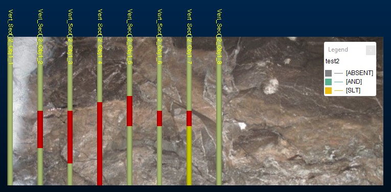
An example of stratigraphic sections displayed in the map sidewall view
Based on the data collected, an indication of geological structures can be automatically visualized. Once rendered, vertical drillholes can be edited, moved or reoriented using simple interactive tools.
Note: You can digitize face map data type using either the 3D map or butterfly map view. Butterfly maps are only available if your configuration permits it.
Object containers, attributes and other configurations for stratigraphic sections are defined in your system configuration file.
The display of sample dimension attributes on this screen is customisable and dependent on your system configuration file. By default, a Length table column permits the length of any sample interval to be specified. The overall length of the sample, as a result, being the sum total of all specified interval lengths. By adjusting your configuration, it is also possible to display the following editable fields:
-
FROM: The distance from the collar from which the new interval begins.
-
TO: The terminal distance of the interval.
Where multiple columns exist,
Note: LENGTH, FROM and TO are default column names. You can choose a different label for your vertical sections table via the system configuration file. Also, columns appear in the table in the top-bottom order they are listed in the same file.
You can also choose which column is highlighted by default (ready for typing) when a new interval is added.
Section Measurements
By default, the length of each vertical section is measured in meters. These values appear (and are edited within) the Length cell of the table grid that appears for each vertical section selection in the table above.
You can also log section lengths in centimetres (cm) using a configuration file parameter like this:
<StratSections segmentLengthsInCm="TRUE">
See Configuration File Reference and Map Objects Configuration.
The Stratigraphic Sections Panel
the panel is split into the following key sections (from top to bottom):
- An upper tool section containing map tools and buttons to access other Mapping task tabs.
- A set of tools dedicated to stratigraphic sections (see below)
- A table containing references to all logged drillholes, attributes and whether an off-face drillhole exists (if permitted),
- A table containing context-sensitive interval information. Typically this is one or more intervals representing rock types and their respective lengths.
Tip: If you are using a portable device, automatically display a screen keyboard for easier data entry at the face. Enable screen keyboard mode using the Setup ribbon's On-Screen Keyboard command.
Create a New Stratigraphic Section Layout:
A stratigraphic section layout consists of one or more vertical drillholes at known intervals, containing one or more categorical intervals per sample.
- Select or create a map and choose the face to receive stratigraphic data.
-
Use the drop down list to choose an object to host stratigraphic data.
Note: Stratigraphic data object containers are defined in your system configuration file.
-
Select Create a new or reset an existing stratigraphic section using the panel icon, or use the same icon on the Stratigraphic Sections ribbon.
Warning: Existing stratigraphic data will be erased if it exists.
The Create New Sections screen displays.
- Choose the direction in which drillholes will be laid out.
- Select From left edge, heading right or;
- Select From right edge, heading left.
Note: You can change how distances are represented in the table after creation using Toggle distance direction.
- Choose how many drillholes to add to the face using Create.
- Choose how far apart drillholes will be added using At every.
- Choose a starting point for the first drillhole either on the left or right of the set. Either enter a distance manually using Starting at or use the pick button to digitize a point on the map (the distance from the left or right of the map is calculated automatically).
-
Click OK.
The map view updates to show new drillhole data. This data is also displayed in your Project Data control bar.
-
Save your project to update the local database contents.
Configure Structural Data for a Vertical Drillhole
Once you have added drillholes to the stratigraphic section map, you can enter vertical distance details representing rock type contact positions. You can also modify existing sample definitions.
To add structural data to the stratigraphic section:
- Select or create a map and choose the face to receive stratigraphic data.
-
Use the drop down list to choose an object containing stratigraphic section data. See Create a New Stratigraphic Section Layout.
-
Select a drillhole object using the upper table.
-
The lower table, containing sample interval data, updates to show information relevant to the selected hole.
-
To add a new sample interval to the drillhole:
-
Click the green "+" at the bottom of the table.
A new sample is added to the end of the channel.
-
Adjust sample Length values.
Note: lengths are calculated, by default, from the top of the hole going downwards. You can change the length values automatically to represent the inverse measurement direction using Toggle length direction afterwards, if required.
-
Adjust other sample attribute values.
Note: Stratigraphic section attributes are defined in your system configuration file.
-
To remove a sample from the selected hole, use the red X on the right of the samples table.
-
To hide a sample from the display, use the check box on the left of the table.
-
Save your project to update the local database contents.
Visualize Structural Outlines
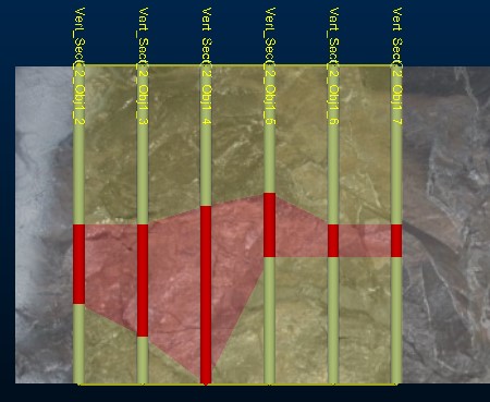
You can visualize the structures implied by logged sample values using the Vertical Section Visualizer. If enabled, 'best-fit' outlines are generated around your sample contact positions.
Note: where structural trends are ambiguous or cannot be deduced from the data provided, fully coincident outlines may not be generated. However, providing sufficient data has been logged, a reasonable correlation can be generated and displayed.
Visualize Structural Outlines
- Select or create a map and choose the face to receive stratigraphic data.
-
Use the drop down list to choose an object containing stratigraphic section data. See Create a New Stratigraphic Section Layout.
-
Configure Structural Data for 2 or more drillholes. Holes must contain sufficient sample data to calculate an outline.
-
Select Toggle visualization to enable outline mode. Outlines will appear around obviously distinct geological structures, for example:
Delete a Stratigraphic Section
To remove all vertical drillholes and their associated sample configuration, click or tap Delete Stratigraphy.
Warning: Stratigraphic section deletion is permanent and can't be recovered.
Delete a Vertical Drillhole
To remove a vertical drillhole and its associated sample configuration, click or tap the red X on the right of the drillholes table.
Warning: Drillhole deletion is permanent and can't be recovered.
Delete a Sample
To remove a sample from a drillhole, click or tap the red X on the right of the samples table.
Warning: Sample deletion is permanent and can't be recovered.
Move Channel Vertically
Existing vertical channels can be moved upwards or downwards along a vertical direction. This command does not consider preselected data.
To Move a Vertical Channel:
- Select or create a map and choose the face to receive stratigraphic data.
-
Use the drop down list to choose an object containing stratigraphic section data. See Create a New Stratigraphic Section Layout.
-
Select Move Stratigraphic Section (either using the Mapping Task Bar or the ribbon button equivalent.
-
Left click and drag any channel on the map. Upwards and downwards dragging will move the channel upwards or downwards, preserving the current Distance.
Related Topics and Activities